Scope
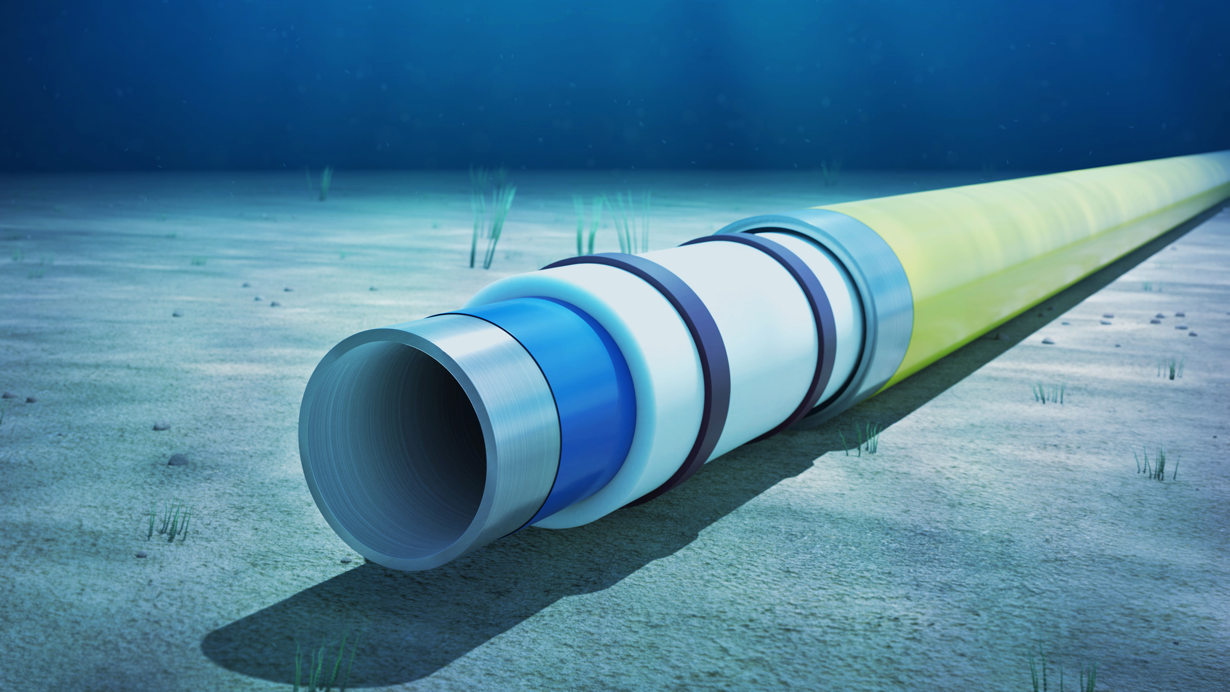
A subsea spool design project required confirmation that a new insulation system would meet the specified thermal performance. The system included insulation for bends, field joints and seven flange cover types. The client needed independent verification that the proposed insulation configurations achieved the maximum allowable U value of 3.48 W/m²K.
The challenge
The insulation system consisted of pre-formed covers that would be retrofitted after spool fabrication and installation, to protect several different components with varying geometry and coating types. Our client was a supplier of insulation products and had developed inhouse calculations to select the insulation thickness for each type of insulation cover. Our clients’ customer had requested that independent analysis be carried out. The verification process needed to be robust, repeatable and aligned with engineering good practice.
Solution
For the bends and field joints, where the cross-section was consistent, Jee reviewed our client’s inhouse calculations to verify the accuracy and completeness of the approach. All inputs, material properties and assumptions were checked and minor improvements were identified to improve reliability for future users.
For the flange covers, Jee developed finite element heat transfer models in Abaqus. Axisymmetric models were built to capture conduction through the steel, coatings, insulation and seawater-filled annulus between the pipe and the cover. The modelling approach accounted for the variation in material thickness along the length of the flanged connection, meaning that thermal hot-spots could be identified to allow optimisation of the insulation thickness.
The models accounted for axial and radial heat transfer which improved on the original design method that only accounted for radial heat transfer. Mesh sensitivity checks were performed using 1.5 mm, 3 mm and 6 mm elements to confirm output stability. Additional analysis was carried out to demonstrate the impact of natural convection effects within the seawater-filled annulus.
Insulation thicknesses were adjusted iteratively until a U-value between 3.40 and 3.45 W/m²K was achieved for each cover.
Benefits and outcomes
Jee verified that the insulation of bends and field joints met the required U value when applying the appropriate insulation thickness. Recommendations were made to refine our client’s inhouse calculation sheet to improve reliability and reduce future scope for errors.
For the flange covers, the models demonstrated that the cover designs could be optimised. Some covers required an increase in insulation thickness to achieve the required U-value, while other covers could benefit from reduced insulation. This insulation reduction saved our client material costs while still meeting the project specification.
Jee delivered a clear and auditable verification of the insulation system, providing confidence in the thermal design before manufacture. The combined spreadsheet review and FEA approach allowed the client to validate all insulation components consistently while also demonstrating compliance with the maximum U-value requirement. The findings enabled the project to progress with assurance that the insulation design would protect operational performance once installed subsea.
For more information or to download our Integrity Management capability statement, visit www.jee.co.uk/design.
To contact our Head of Design, John French, email John.French@jee.co.uk , or call +44 (0)1732 371 371.

 Jee Ltd

-1.png)